Web-interface
A web interface is necessary for the initial configuration of the gateway, viewing the log, adding new devices, etc.
Home
The Home page shows the main statuses of the controller 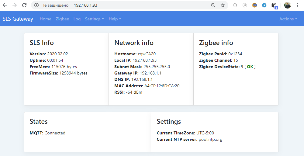
Zigbee
A page with a list of paired devices.
nwkAddr - The address of the device on the network. The coordinator always has the address 0x0000.
FriendlyName - The friendly name of the device on the network.
ieeeAddr - The physical address of the device on the network. ManufName - Name of the manufacturer.
ModelId - Symbol of the device model.
LinkQuality - Estimates of the quality of communication.
Interview - The process of obtaining the source data from the device at the first binding of the device to the gateway.
LastSeen - The time that has passed since the last message from the device.
Routes - The address of the device that is the router. PS - Battery charge in%, provided that the device is powered by a battery. If the device is powered from the network, the ≈ icon is displayed Actions: device management. Delete device, set name
Back - return to the previous page. Refresh - Refresh the current page. Groups - create, edit, delete groups. (Under development)
Setup - setting the channel number and PanId. Ability to select the format of the transmitted data MQTT.
Start Join - start the pairing mode of devices within 255 seconds.
![zigbee] (/img/slszigbee.png)
Zigbee settings page ![zigbee] (/img/slszigeesetup.png)
Log
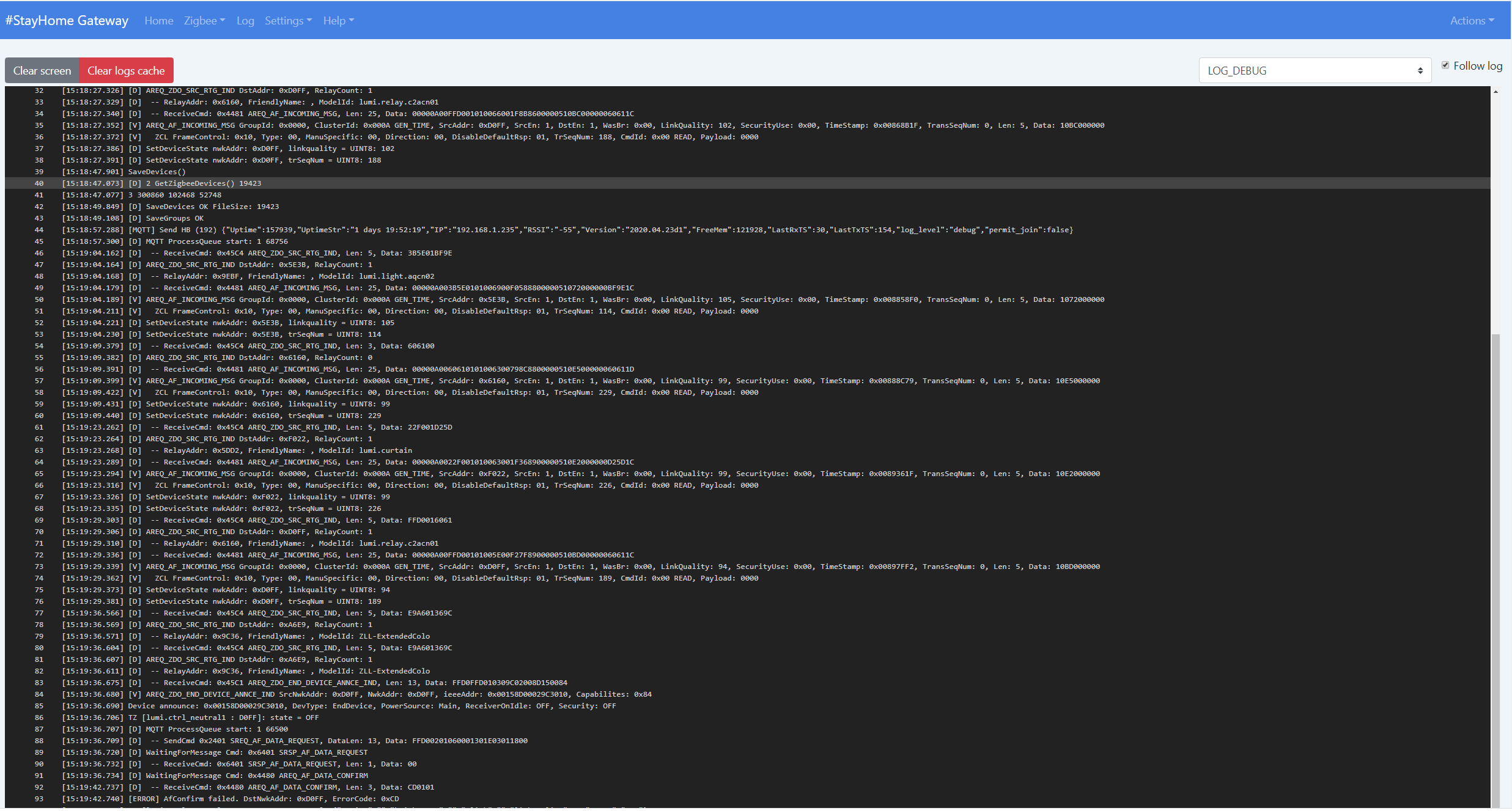
On the log page, you can see the latest system messages.
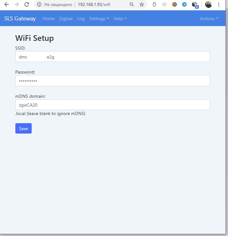
Settings -> Wifi Setup
On this page you can set Wi-Fi network parameters:
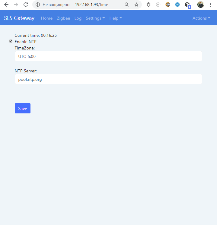
Settings -> Time Setup
On this page, you can configure the time zone and the time synchronization server.
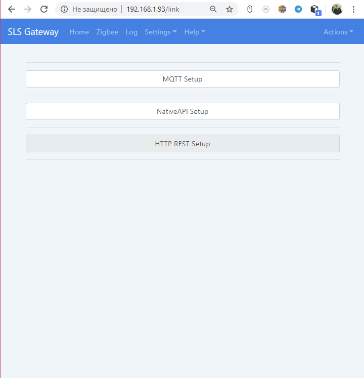
Settings -> Link Setup
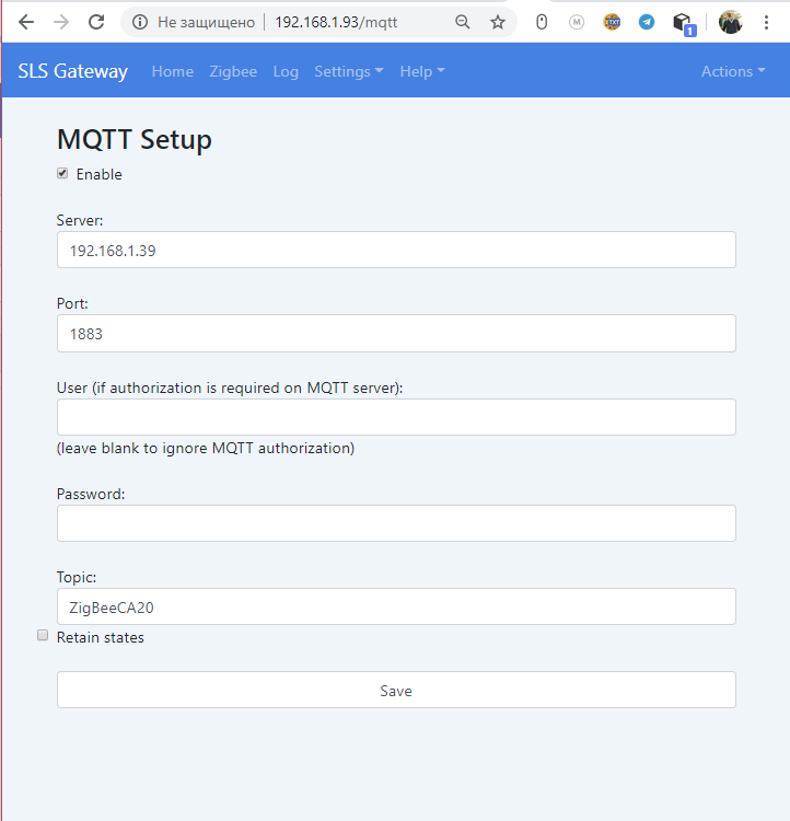
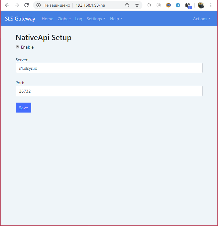
Server settings MQTT, NativeApi and RestApi.
Settings -> HW Setup
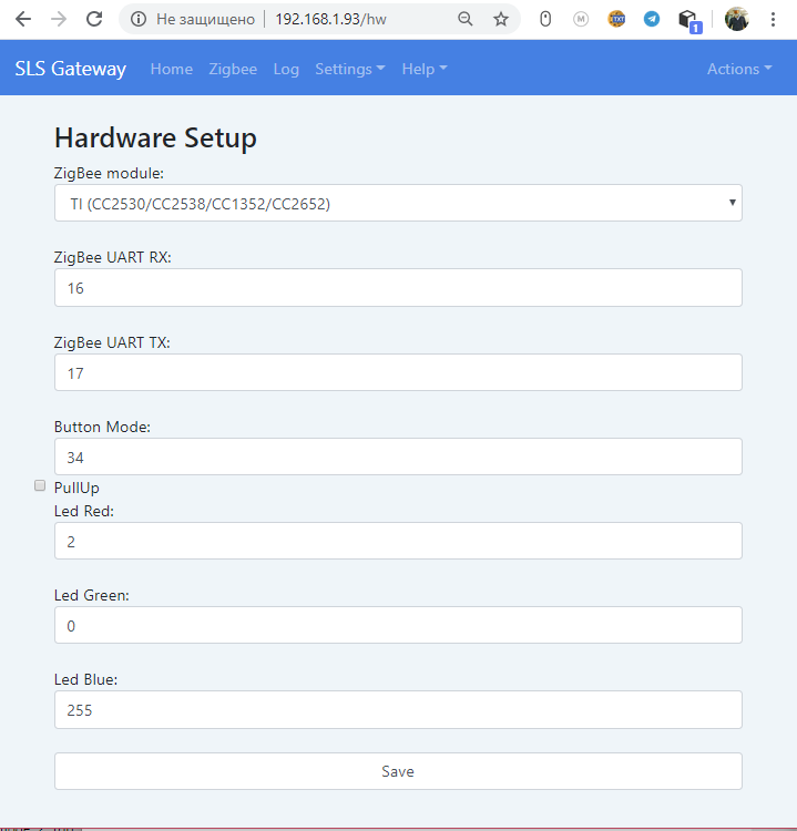
Gateway hardware settings.
In this menu, you can select the type of Zigbee TI or NXP module, as well as specify the GPIO numbers of the ESP32 module (RX, TX)
Hardware buttons. (if the button is pulled to the ground, and when you press it, the input of the ESP32 is 3.3V, then you need to check the PullUp box.
Red LED. (lights up when a message arrives from the end zigbee device)
Green LED. (lights up when Join mode is active)
Blue LED.
Action -> Update
Updating gateway firmware by OTA. 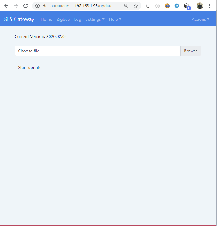
Action -> Reset
Reset - reset to the initial state. 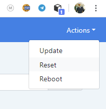
Action -> Reboot
Reboot - reboot the gateway.

 SLS Smart Home